Timz Ham Radio Page Yaesu FTM-400 / Yaesu FTM-350 / Yaesu FT-90R / THD-72A / DR-535 / IC-7100 / Wouxun KG-UV8E Tri-Band / Main
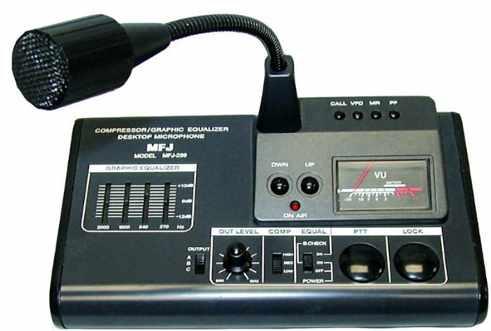
MFJ-299 Deskmic Console
I generally put the FAQ at the end of my pages; but in this specific I will start out with it:
* Can you connect multiple radios to this MFJ-299?
Yes and No, please read on...* Can you have more than one radio connected at the same time?
No* Tim, I think you misunderstood something in the instructions... let me be more specific; can you have up to three radios connected at the same time... as long as one is a Icom brand, another a Kenwood, and the third one a Yaesu?
No. One radio at any one time; verified with MFJ.* if you can't have multiple radios connecterd, then what is the purpose of the A,B,C selector switch?
I was told by MFJ that there is no schematic available for the 299. From my best guess, the selector switch sets some freq response & level variables. Also, in position C (Yaesu) it modifies the PTT line to conform to Yaesu's uniqueness.* Do you have to use a 9v battery?
to my surprise, no. Please continue below...
My modified MFJ-299
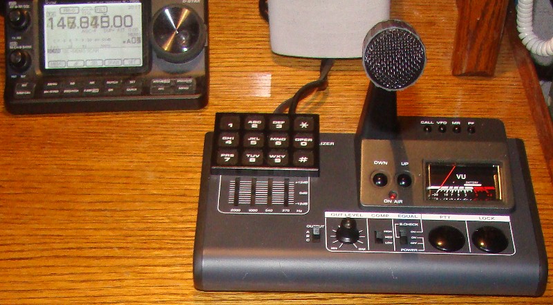
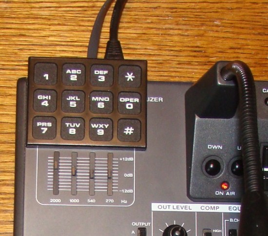
I added a DTMF encoder; this one is a CES 220L-01 purchased new on eBay. This encoder has a backlit keypad, and provides a PTT when any keypad button is pressed.
Although there is a A,B,C selector switch... and three jacks on the rear of the unit...
you can only have a single radio connected. The MFJ-299 is designed to operate one radio, and only one radio. If you were like me... you purchased this device thinking you could move the A,B,C selector switch... and this would activate just one of the three jacks connecting to multiple radios. What I found is that all three jacks send out a PTT simultaneously, regardless of the position of the A,B,C switch. After re-reading the MFJ ads for this deskmic console, they do not mention anything about having multiple radios connected.
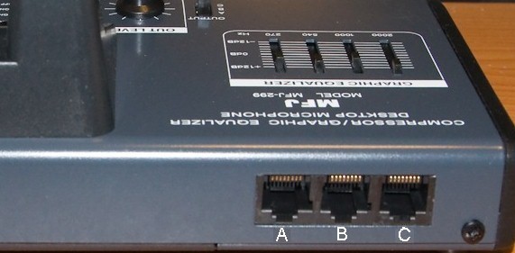
Note: Jack A is reserved for Icom radios. I ran a straight-through 8 pin cable w/RJ-45 connectors on each end and it works perfect on my Icom IC-7100. I first tried an ethernet cable and it worked too; but was way too long. So I crimped up a shorter cable for this. To my surprise, the 299 powered-up with the Icom 7100 connected, without a 9v battery installed. Whenever the Icom 7100 is powered, the 299 is also. The 299 performs fine with this being the only voltage source, and this is a good power source no matter what position the A,B,C selector switch is in. These days almost all mobile/base radios mic jacks have one pin that outputs voltage... to power something in the microphone. Apparently the 299 utilizes this voltage and can power itself from this. When connecting up the second radio (Jetstream), I purposely did not connect the wire from the Jetstream mic jack that carried control voltage. I don't know if the MFJ-299 three jacks have this VCC line isolated from each other or not; so I played it safe by only allowing one radio to supply voltage to the 299.
Jack B is reserved for Kenwood radios. I do have a second radio attached to this B jack, it is a Jetstream 220 mobile and not a Kenwood. Again, I made a cable, going from the Jetstream octal 8 pin mic connector to the 8 pin RJ45 on the deskmic... using 3 wires only (PTT, GND, and TX mod) It works perfectly. I do not have a third radio connected.
I imagine you're now saying: "but I though you said you couldn't have multiple radios connected at the same time?".
I modified it.
The A,B,C selector switch is a 3 position - 4 pole switch. Only 3 of the poles are used, so that leaves one pole open for whatever you want to switch with it. What I did was disconnect the PTT from going to the rear 3 jacks... and placed this signal on the center of the unused pole of the 3 way switch. Then ran individual PTT wires to the 3 jacks. So now, in position A... only the A jack (my Icom 7100) will be given a PTT. In position B... only the Kenwood jack B (in my specific it's a Jetstream mobile) is the only radio getting a PTT.This seemed easy to do at first (actually allowing multiple radios to be connected at the same time)... but the issue was with the 3 jacks on the rear of the unit. All three are on a single circuit board, and the connecting PTT trace runs on the side of the board where the actual jacks are... underneath them. To access this PTT trace (and cut it to seperate the PTT signals) you will need to remove 2 of the jacks so that you can access & cut the trace that connects all the PTT's together. You have to isolate all three jacks PTTs in order to allow multiple radios connected simultaneously.
email Tim